I recently bought an old FT-817 with the intent of using it to get back on the linear satellites. Upon receiving it, I found that no matter which connector I set the antenna output to (front or rear), it always transmitted from the rear SO-239 antenna connector. As my intention is to use the front BNC antenna connection for satellite purposes, this is not ideal! After Googling around a bit, I learned I am not the first person to encounter this problem.
On the FT-817, the relay is connected so that when it is de-energized, it is connected to the front BNC connector. When set to the rear antenna connector in the menu, it applies power to the relay to switch it to the SO-239. Some on a Groups.io thread have theorized that using the radio extensively on the SO-239 connector, as is probably likely for most users, could cause the relay to become magnetized in such a way that it won’t switch back to the BNC connector. In any event, the fix is to change the relay out.
 Another Groups.io discussion led to a viable replacement part number for the relay, Panasonic RK1-9V ARK115. Of course, the relay is obsolete and not available from any of the usual suspects like Digi-Key or Mouser, but I did find it on eBay for about $20 with shipping from China. After completing this fix, I learned from a friend that at least as of earlier in 2024, you could still buy the relay from Yaesu’s parts department directly for a similar price with shipping (it actually was a little cheaper if I recall correctly). After waiting a few weeks for delivery, I started opening up the FT-817 to make the swap.

The BNC needs to come out of the front panel and the tape pulled up to allow the bottom PCB to be removed.
While the FT-817 Service Manual is readily available online, from my quick (probably too quick) look at it, I didn’t see exactly how to access the relay so I tried removing the Main board only to realize there is no mechanical connection to the PA/Final board on the bottom of the radio. However, after putting the main board back in, I found I did need to remove it to pull off the tape holding down the coax to the BNC front panel to allow the PA/Final board to be removed enough to access the bottom of the board, so both boards do need to be removed in the end. Additionally, this meant the front panel of the radio had to be removed. So in the end, basically the entire radio needed to be disassembled to access the relay in question. You also need to unsolder the center conductor of the SO-239 to pull of the radio board.
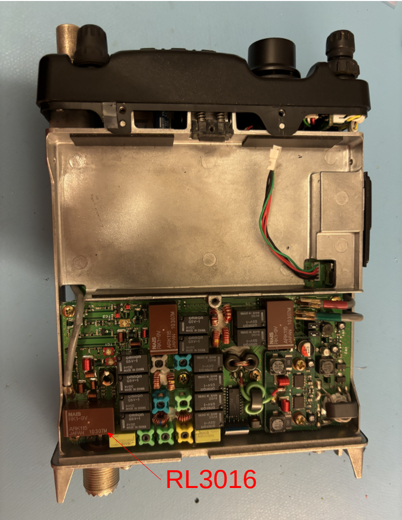
Once the board was free, I got to work desoldering the old relay, RL3016. This proved to be difficult as there were several pins on a ground plane, and I didn’t want to cook any nearby parts. After adding some extra solder as a helper and using my solder wick judiciously, I was able to work the relay out. This was by far the most difficult part of the process. After it was gone, I was quickly able to put in the new relay and then put the radio back together.
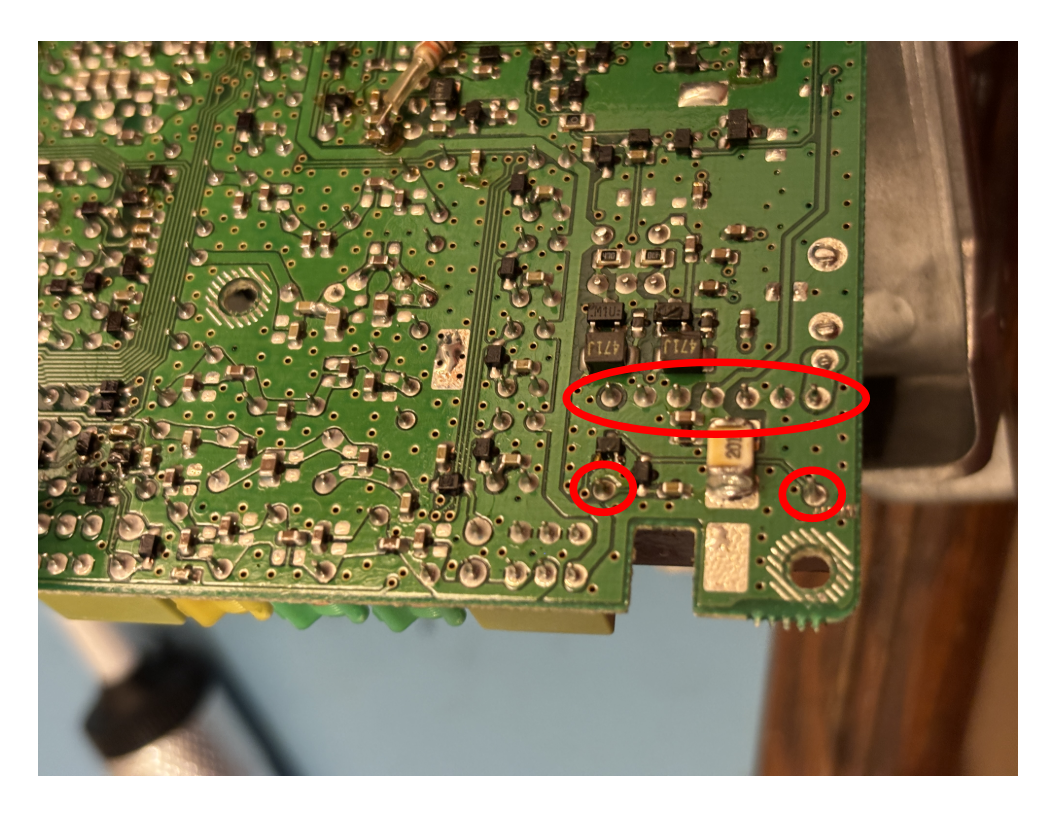
There are nine pins that need to be desoldered to remove RL3016.
After powering up, I tried switching the menu item for antenna connector between front and back and heard a nice click as I did so. Success! I then tested a dummy load on each port and tried both settings on several bands and all was expected.
This fix wasn’t too bad once I figured out exactly how to get to the parts, but with the difficulty in desoldering the relay itself, I certainly wouldn’t recommend this to a beginner. Also, I would caution anyone who does this to be gently with the radio due to a lot of fragile parts inside. For instance, there is a three-pin header that goes between the main board and RF board that is easy to bend when you’re putting it back together, as well as a toroid near the PA submodule board that had broken free from its glued position on the PCB. With a radio of this age and density, it may be worth some preventative maintenance while you have it opened up and taking a look at points with mechanical stress.
Great walkthrough on replacing the antenna switch relay on the FT 817 and keeping older gear running strong. I’ve found that ensuring solid physical connections in any RF or antenna setup makes a noticeable difference in performance. Using quality coax connectors and proper preparation tools helps maintain signal integrity and prevents issues down the line. Small details in connection hardware can really improve how reliable your setup feels over time.